| T-Series | HOME ▶ PRODUCT ▶ STEERING GEAR ▶ T-Series |
 |
|
|
|
|
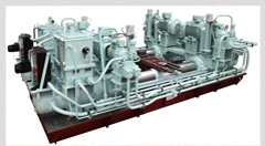 | | YDFT-1000-4 |
|
|
| ● System configuration and Functions. |
|
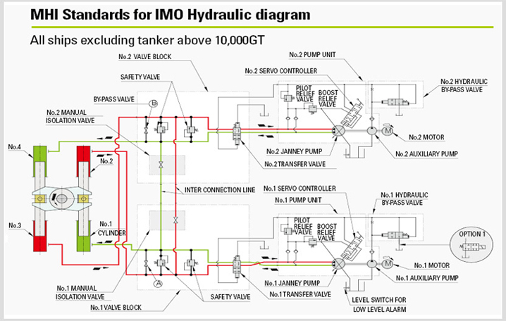
| 1. | In both the 1-ram 2-cylinder and the 2-ram 4-cylinder types, the rudder actuator has a total capacity (torque) to be equivalent to the 100% of design capacity and the power system is completely doubled. |
| 2. | When a single failure, such as the oil leakage, occurs in the piping system, the low oil level detector of the oil tank to be connected to the power system in operation is actuated to send an alarm to the bridge and engine room. The valve adjustment of A~F on the next page diagram is then done manually in the steering gear room in order to isolate the malfunctioning hydraulic system. Thus maintaining stable operation of the power system. In this manner, steering capacity is maintained. |
| 3. | It is satisfies the IMO regulation for the tankers of 10000 GT or more, that the valves A and B Change to the automatic isolation valves. In that case, when a single failure, such as the oil leakage, occurs in the piping system, by the low oil level detector of the oil tank to be connected to the power system in operation, the other power system is simultaneously operated automatically or remotely. At the same time, the circuit isolation valves between the circuits actuate to isolate the malfunctioning piping system automatically. Thus, the steering capability is maintained. And the power system on the malfunctioning piping system is stoped automatically by the second low level detector, At the same time, the related isolation valve also returns to its original position. |
| 4. | Alter the single failure to be described above, the capacity of rudder actuator is reduced to the half of design capacity. It is necessary to reduce ship's speed to the half of max. speed or below 7 knots. |
|
|
 |
|
 |
|
 |
|
| ● Features |
|
 |
| 1. Excellent Response and Energy-Saving |
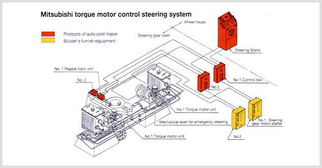
| The torque motor system enables the steering gear to respond more accurately and more quickly to the steering command from steering stand than the hitherto-employed mechanical link system, especially, in fine rudder angle. The pay off : into propensity of the ship meandering, hence no waste of precious fuel. |
| 2. Simple Construction and Compact Design |
| Pump the discharge is controlled electrically by the torque motor. Without the auto-pilot receiver and mechanical link of the conventional system, the new system is simple in construction and compact in design. |
| 3. High Reliability |
| The torque motor employed is the brushless, gearless type and a D,C motor with to rubbing parts. Non-follow-up steering by-passing the amplifier can be preformed from the bridge. The hydraulic system remains identical to that of the conventional steering gear of proven design, with mechanical feedback links. |
| |
|
| 4. Greater Freedom of Arrangement |
| It is devoid of the auto-pilot receiver and mechanical link hitherto to be required in this system, the arrangement of pump units can make with a greater degree of freedom, besides the ease of outfitting on board. |
| 5. Ease of Control in Emergency Steering |
| Emergency steering can be performed with the mechanical handle on the servo mechanism on the pump, with only limited physical effort. |
| 6. No-Load Motor Start-up |
| Since the motor of the hydraulic pump can be started in the no-load condition, the emergency generator can be designed just that much smaller in capacity. |
| 7. Complete Dual Control System |
| The complete control system is demanded from the rule of ABS and other classification societies to be satisfied the limit of specification for the standard design. |
|
| ● Operation |
|
| ■ Bridge Remote Control |
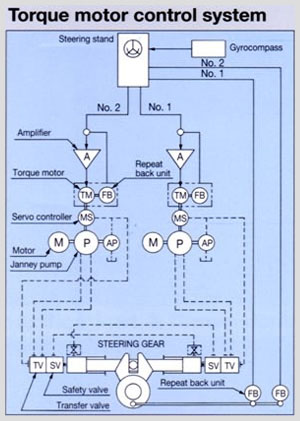
The rudder angle electric command signal issued from the steering stand is amplified by the amplifier (A) and transmitted to the torque motor (TM).
The torque motor then drives the hydraulic pump control mechanical servo (MS) only as much as is directed by the command signal so that the tilting plate of the hydraulic pump (P) will be inclined accordingly for discharge of the required quantity of working oil.
The working oil pressure thereby exerted causes the rudder to turn, and with feedback signal form the rudder tiller transmitted from the feedback detector (FB) to the steering stand signalling the rudder reaching the angle directed by the command signal the torque motor drives the mechanical servo back to the neutral position (0 deg).
Consequently the hydraulic pump tilting plate also will return to the uninclined neutral position where the oil suction and discharge no longer take place, and the rudder therefore will be held at the angle to which it has been turned. |
|
| ■ Local Control by the means of Mechanical Handle |
In the local ‘HAND' control mode, it is not by the electric command signal but by direct manipulation of the mechanical handle on the hydraulic pump control mechanical servo that the hydraulic pump discharge is controlled.
Since it is non-follow-up steering in this instance, releasing the mechanical handle upon turning the rudder to the desired angle will cause the mechanics servo centering function to automatically bring the hydraulic pump tilting plate back to the neutral positron so that the rudder will be kept at the desired angle, |
|
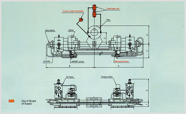
| ● SFT-Type |
|
 |
|
| ■ Specifications & Dimensions |
|
| |
Type |
|
SFC-30 |
SFC-40 |
SFC-60 |
SFC-80 |
SFC-125 |
SFC-170 |
| |
Torque at maximum
working pressure |
t-m |
32 |
45 |
53 |
63 |
72 |
86 |
105 |
122 |
143 |
176 |
| KN-m |
314 |
441 |
520 |
618 |
706 |
844 |
1030 |
1196 |
1402 |
1726 |
Rudder turming
speed |
deg/sec |
65/28 |
|
| Normal tiller radius |
mm |
470 |
520 |
580 |
|
650 |
|
730 |
|
850 |
|
| Diameter of ram |
(ф)mm |
170 |
195 |
220 |
|
240 |
|
270 |
|
300 |
|
Maximum working
oil pressure |
kgf/㎠ |
220 |
220 |
180 |
215 |
185 |
220 |
190 |
220 |
180 |
220 |
| Mpa |
2106 |
21.6 |
17.6 |
21.1 |
18.1 |
21.6 |
18.6 |
21.6 |
17.6 |
21.6 |
Safety valve
pressure
(Design pressure) |
kgf/㎠ |
275 |
275 |
225 |
269 |
232 |
275 |
238 |
275 |
225 |
275 |
| Mpa |
27.0 |
27.0 |
22.1 |
26.4 |
22.7 |
27.0 |
23.3 |
27.0 |
22.1 |
27.0 |
With
main
stand
-by
pump |
motor |
Output x
Number |
Kw |
11x2 |
15x2 |
15x2 |
19x2 |
22x2 |
25x2 |
30x2 |
37x2 |
45x2 |
50x2 |
Number of
revolations |
rpm |
1,800 |
|
| Overload |
%/sec |
100/60 |
|
| Pump Type x Number |
06V-FH2MK x 2 |
1V-FH2MK x 2 |
Without
stand
-by
pump |
motor |
Output x
Number |
Kw |
7.5x2 |
11x2 |
11x2 |
15x2 |
15x2 |
19x2 |
22x2 |
25x2 |
Number of
revolations |
rpm |
1200 |
1800 |
| Overload |
%/sec |
100/60 |
| Pump Type x Number |
06V-FH2MK x 2 |
| |
Dimensions |
mm |
A |
2026 |
2220 |
2395 |
2600 |
2900 |
3235 |
| B |
2025 |
2185 |
2360 |
2565 |
2865 |
3200 |
| C |
470 |
520 |
580 |
650 |
730 |
850 |
| D |
740 |
815 |
910 |
1015 |
1140 |
1315 |
| E |
760 |
760 |
760 |
760 |
910 |
910 |
| F |
190 |
205 |
220 |
240 |
260 |
285 |
| G |
1243 |
1253 |
1265 |
1283 |
1420 |
1440 |
|
Note : The above list is complied for the turning angle of rudder, ±35 deg, and the electric source is the 60Hz.
This steering gear have the special particulars by the high workmanshop design. |
|
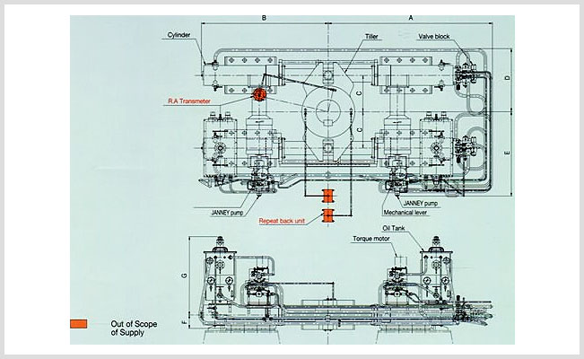
| ● DFT-Type |
|
 |
|
| ■ Specifications & Dimensions |
|
| |
Type |
|
DFT-60 |
DFT-80 |
DFT-125 |
DFT-170 |
| |
Torque at maximum
working pressure |
t-m |
52 |
62 |
74 |
91 |
105 |
126 |
140 |
172 |
| KN-m |
510 |
608 |
726 |
892 |
1030 |
1236 |
1373 |
1687 |
Rudder turming
speed |
deg/sec |
65/28 |
| Normal tiller radius |
mm |
470 |
520 |
580 |
650 |
Maximum working
oil pressure |
kgf/㎠ |
185 |
220 |
180 |
220 |
180 |
215 |
180 |
220 |
| Mpa |
18.1 |
21.6 |
17.7 |
21.6 |
17.7 |
21.1 |
17.7 |
21.6 |
Safety valve
pressure
(Design pressure) |
kgf/㎠ |
232 |
275 |
225 |
275 |
225 |
269 |
225 |
275 |
| Mpa |
22.7 |
27.0 |
22.2 |
27.0 |
22.2 |
26.4 |
22.2 |
27.0 |
With
main
stand
-by
pump |
motor |
Output x
Number |
Kw |
15 x 2 |
18.5 x 2 |
22 x 2 |
25 x 2 |
30 x 2 |
37 x 2 |
45 x 2 |
50 x 2 |
Number of
revolations |
rpm |
1,800 |
| Overload |
25% - Continuous, 100% - 1 Hour, 200% - 60 sec |
| Pump Type x Number |
06V-FH2B-MK x 2 |
1V-FH2B-MK x 2 |
Without
stand
-by
pump |
motor |
Output x
Number |
Kw |
11x2 |
11 x 2 |
15 x 2 |
15 x 2 |
19 x 2 |
22 x 2 |
25 x 2 |
Number of
revolations |
rpm |
1,800 |
| Overload |
25% - Continuous, 100% - 1 Hour, 200% - 60 sec |
| Pump Type x Number |
06V-FH2B-MK x 2 |
| |
Dimensions |
mm |
A |
1826 |
1931 |
2164 |
2344 |
| B |
1678 |
1838 |
2011 |
2213 |
| C |
470 |
520 |
580 |
650 |
| D |
973 |
1023 |
1083 |
1153 |
| E |
1460 |
1510 |
1585 |
1660 |
| F |
190 |
205 |
220 |
240 |
| G |
1240 |
1250 |
1265 |
1280 |
|
Note : The above list is complied for the turning angle of rudder, ±35 deg, and the electric source is the 60Hz.
This steering gear have the special particulars by the high workmanshop design. |
|
 |
|
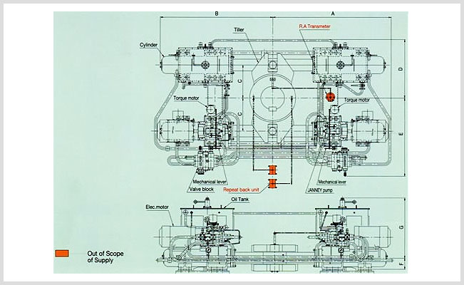
| ■ Specifications & Dimensions |
|
| |
Type |
|
DFT-200 |
DFT-250 |
DFT-300 |
DFT-335 |
| |
Torque at maximum
working pressure |
t-m |
207 |
244 |
291 |
351 |
| KN-m |
2030 |
2393 |
2854 |
3442 |
Rudder turming
speed |
deg/sec |
65/28 |
| Normal tiller radius |
mm |
715 |
730 |
780 |
850 |
Maximum working
oil pressure |
kgf/㎠ |
220 |
220 |
220 |
220 |
| Mpa |
21.6 |
21.6 |
21.6 |
21.6 |
Safety valve
pressure
(Design pressure) |
kgf/㎠ |
275 |
275 |
275 |
275 |
| Mpa |
27.0 |
27.0 |
27.0 |
27.0 |
With
main
stand
-by
pump |
motor |
Output x
Number |
Kw |
55 x 2 |
75 x 2 |
80 x 2 |
90 x 2 |
Number of
revolations |
rpm |
1,200 |
| Overload |
25% - Continuous, 100% - 1 Hour, 200% - 60 sec |
| Pump Type x Number |
3V-FH2B-MK x 2 |
Without
stand
-by
pump |
motor |
Output x
Number |
Kw |
30 x 2 |
37 x 2 |
45 x 2 |
50 x 2 |
Number of
revolations |
rpm |
1,800 |
| Overload |
25% - Continuous, 100% - 1 Hour, 200% - 60 sec |
| Pump Type x Number |
06V-FH2B-MK x 2 |
1V-FH2B-MK x 2 |
| |
Dimensions |
mm |
A |
2533 |
2740 |
2988 |
3100 |
| B |
2386 |
2505 |
2655 |
2842 |
| C |
715 |
730 |
780 |
850 |
| D |
1320 |
1335 |
1384 |
1454 |
| E |
1872 |
1887 |
1937 |
2007 |
| F |
255 |
260 |
275 |
285 |
| G |
1280 |
1295 |
1305 |
1315 |
|
Note : The above list is complied for the turning angle of rudder, ±35 deg, and the electric source is the 60Hz.
This steering gear have the special particulars by the high workmanshop design. |
|
 |
|
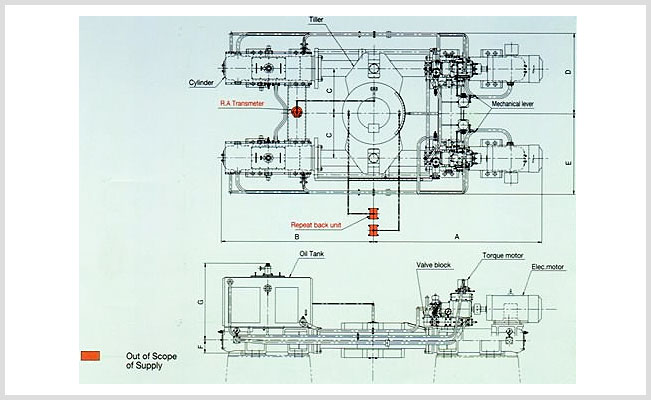
| ■ Specifications & Dimensions |
|
| |
Type |
|
DFT-400 |
DFT-475 |
DFT-530 |
| |
Torque at maximum
working pressure |
t-m |
363 |
400 |
440 |
485 |
560 |
| KN-m |
3560 |
3923 |
4315 |
4756 |
5492 |
Rudder turming
speed |
deg/sec |
65/28 |
| Normal tiller radius |
mm |
900 |
940 |
970 |
Maximum working
oil pressure |
kgf/㎠ |
195 |
215 |
200 |
220 |
220 |
| Mpa |
19.1 |
21.1 |
19.6 |
21.6 |
21.6 |
Safety valve
pressure
(Design pressure) |
kgf/㎠ |
244 |
269 |
250 |
275 |
275 |
| Mpa |
23.9 |
26.4 |
24.5 |
27.0 |
27.0 |
With
main
stand
-by
pump |
motor |
Output x
Number |
Kw |
110 x 2 |
110 x 2 |
132 x 2 |
150 x 2 |
160 x 2 |
Number of
revolations |
rpm |
1,200 |
| Overload |
25% - Continuous, 100% - 1 Hour, 200% - 60 sec |
| Pump Type x Number |
6V-VH2B-MK x 2 |
Without
stand
-by
pump |
motor |
Output x
Number |
Kw |
50 x 2 |
55 x 2 |
63 x 2 |
75 x 2 |
75 x 2 |
Number of
revolations |
rpm |
1,200 |
| Overload |
25% - Continuous, 100% - 1 Hour, 200% - 60 sec |
| Pump Type x Number |
3V-FH2B-MK x 2 |
| |
Dimensions |
mm |
A |
3176 |
3455 |
3595 |
| B |
3155 |
3205 |
3255 |
| C |
900 |
940 |
970 |
| D |
1645 |
1685 |
1715 |
| E |
2060 |
2110 |
2160 |
| F |
260 |
275 |
285 |
| G |
1515 |
1520 |
1530 |
|
Note : The above list is complied for the turning angle of rudder, ±35 deg, and the electric source is the 60Hz.
This steering gear have the special particulars by the high workmanshop design. |
|
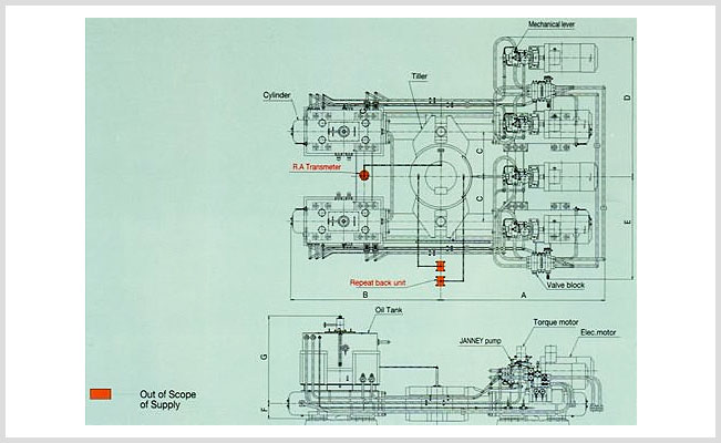 |
|
| ■ Specifications & Dimensions |
|
| |
Type |
|
DFT-660 | DFT-680 |
DFT-760 |
DFT-870 |
DFT-1000 |
DFT-1250 |
| |
Torque at maximum
working pressure |
t-m |
660 |
680 |
768 |
872 |
1002 |
1179 |
| KN-m |
6473 |
6669 |
7532 |
8552 |
9827 |
11562 |
Rudder turming
speed |
deg/sec |
65/28 |
| Normal tiller radius |
mm |
1050 | 1050 |
1100 |
1130 |
1180 |
1240 |
Maximum working
oil pressure |
kgf/㎠ |
220 |
220 |
220 |
220 |
220 |
220 |
| Mpa |
21.6 |
21.6 |
21.6 |
21.6 |
21.6 |
21.6 |
Safety valve
pressure
(Design pressure) |
kgf/㎠ |
275 |
275 |
275 |
275 |
275 |
275 |
| Mpa |
27 |
27 |
27 |
27 |
27 |
27 |
With
main
stand
-by
pump |
motor |
Output x
Number |
Kw |
90 x 4 |
90 x 4 |
110 x 4 |
125 x 4 |
150 x 4 |
160 x 4 |
Number of
revolations |
rpm |
1,200 |
| Overload |
25% - Continuous, 100% - 1 Hour, 200% - 60 sec |
| Pump Type x Number |
3V-FH2B-MK x 4 |
6V-FH2B-MK x 4 |
Without
stand
-by
pump |
motor |
Output x
Number |
Kw |
90 x 2 |
90 x 2 |
110 x 2 |
125 x 2 |
150 x 2 |
160 x 2 |
Number of
revolations |
rpm |
1,200 |
| Overload |
25% - Continuous, 100% - 1 Hour, 200% - 60 sec |
| Pump Type x Number |
3V-FH2B-MK x 2 |
6V-FH2B-MK x 2 |
| |
Dimensions |
mm |
A |
3504 | 3504 |
3658 |
3724 |
3872 |
4123 |
| B |
3504 | 3504 |
3890 |
3717 |
4040 |
4170 |
| C |
1050 | 1050 |
1100 |
1130 |
1180 |
1240 |
| D |
2242 | 2242 |
2449 |
2479 |
2529 |
2589 |
| E |
2242 | 2242 |
2449 |
2479 |
2529 |
2589 |
| F |
325 | 325 |
335 |
345 |
355 |
420 |
| G |
1490 | 1490 |
1620 |
1620 |
1620 |
1645 |
|
Note : The above list is complied for the turning angle of rudder, ±35 deg, and the electric source is the 60Hz.
This steering gear have the special particulars by the high workmanshop design. |
|
